Friday, May 13, 2016

HVAC 1 - Heating and Cooling Equipment

Warning: This is another of my more technical posts.  There are no pretty pictures.

This post addresses two parts of the HVAC system, the Heating and the Air Conditioning.  The other part of HVAC, Ventilation, will be addressed in another post.

In Michigan, most people install a natural gas forced air furnace and air conditioning.  Those willing to spend money on a premium system consider radiant floor heating.  However, highly insulated houses have some differences from typical houses which can change what types of heating a cooling systems are appropriate.  Homes which take insulation and air tightness to extremes, such as those that conform to the Passivehaus standard, usually end up with different types of heating and cooling systems, such as one or two mini-split ductless heat pumps.  In terms of insulation, this house falls into a middle ground between typical houses and Passivehaus houses.  So, it wasn’t obvious whether our systems should be like typical houses, like Passivehaus houses, or some other choice.  (Well, maybe it would have been obvious to someone with less tendency than me to over-think these things.)

Highly insulated houses have a much lower heating demand than typical houses.  Why wouldn’t they just use smaller versions of same types of systems that typical houses use?
  •  Mainstream HVAC equipment manufacturers don’t attempt to serve the highly insulated house market.  The range of equipment sizes offered is based on typical house heating loads.  In fact, most equipment installed in typical houses is considerably oversized.
  •  Distributing heat is easier in a highly insulated house since the heat is not escaping as quickly.  That opens up some possibilities.  However, the warm floor feeling that many people like about radiant floor heating would not be so noticeable in a highly insulated house.
  •  People interested in net-zero homes prefer all-electric systems, which can be supplied by PV panels.
  • Ironically, spending more for highly efficient equipment is less likely to pay off in a low load home.  People who have spent extra money for insulation may want to recoup some of that by spending less on heating and cooling equipment.

For any type of equipment, the first step is to calculate the design heating and cooling loads.  The heating load includes heat lost through walls, windows, ceiling, etc. due to conduction and also heat lost due to air leakage and forced ventilation.  For my location, the design heating load is calculated at 7 degrees F.  Although the temperature gets colder than this, it rarely stays colder than this for long periods.  The design heating load ignores various internal heat gains like solar gain through the windows, use of the fireplace, appliances, and people.  These heat gains, and the thermal mass of the house and contents, sustain the inside temperature when the outside temperature drops below the design temperature.  Also, the equipment is usually sized at least a little larger than the design heating load.  The design heating load came out to 34,000 btu/hr.  The design cooling load, which is calculated at 88 F, came out at 18,000 btu/hr.  Design cooling load does include some internal gains.

The first option I considered was a ground source heat pump (sometimes called a geothermal heat pump).  Instead of creating heat by burning fuel, a heat pump moves heat that already exists.  To move a btu of heat from a cold place to a warm place requires energy but, if the temperature difference is small enough, it requires less than a btu of energy.  The advantage of a ground source heat pump is that the heat is being moved from the ground which, in theory, is a constant, moderate temperature.  The heat is extracted from the ground by fluid that flows through buried tubes.  In summer, the same process is used to transfer heat into the ground to provide air conditioning.  Unfortunately, heat transfer from solid ground is not very efficient.  A lot of tube must be buried to transfer enough heat, which gets expensive.  Even then, the temperature of the dirt near the tubes is not constant due to the heat being extracted.  I was dissuaded by a number of articles on Green Building Advisor that found that the extra efficiency of a ground source heat pump relative to a modern air source heat pump is not worth the additional cost.

That takes me to the next option I considered – mini-split heat pumps.  These move heat from the outside air.  Traditionally, air source heat pumps have been out of favor in cold climates because the capacity and efficiency declines when the outside temperature gets lower.  However, technical advances have made them a practical cold climate alternative.  A ductless mini-split provides the conditioned air directly to the room as opposed to blowing air through ducts.  This improves efficiency but requires equipment on the wall which raises an aesthetic concern.  Another issue is how well the heat is distributed from these units to other rooms.  A ducted mini-split can serve several rooms though a small duct network.  Ducted units give up a little of the efficiency but improve heat distribution.  One thing that builders of super-insulated houses like about mini-splits is that they are available in small capacities – as low as 6000 btu/hr.  They use electricity instead of natural gas which is great if you want to use PV panels to achieve net zero.  In Michigan, however, electricity is much more expensive than natural gas.

A related option is an air-to-water heat pump, such as the Chilltrix system.  Whereas a mini-split relies on refrigerant lines between the outdoor unit and the indoor unit, an air-to-water heat pump retains all of the refrigerant within the outdoor unit.  The heat is transferred between indoor and outdoor units by water lines.  This enables smaller indoor units.  Other than this distinction, the advantages and disadvantages of air-to-water heat pumps are similar to those of mini-split heat pumps.

Eventually, a fuel price comparison convinced me that a natural gas solution made more sense than an electric solution.  Some builders of low load homes have taken advantage of relatively low natural gas prices by installing a combination space heating and domestic hot water system (sometimes called a combi-system).  Domestic hot water is supplied by an efficient natural gas water heater, such as an HTP Phoenix Light Duty.  Hot water is circulated through coils in a hydronic air handler to provide space heating.  Trying to get local contractors to quote and install a combi-system proved difficult.

In the end, I decided on a conventional natural gas furnace.  The smallest size most companies offer in most models, including their modulating models, is 60,000 btu/hr.  (An exception is a Canadian company called Dettson that sells modulating furnaces starting at 15,000 btu/hr.  I ended up ruling out this option due to unfamiliarity to local contractors.)  However, some two-stage high efficiency furnaces are available with an input capacity of 40,000 btu/hr.  The output capacity is 25,000 btu/hr on low stage and 39,000 btu/hr on high stage which is a good match for the house’s heating load.  The smallest available air conditioning unit is 1 ½ tons which is a good match for the cooling load.


The British say that Americans can be counted on to do the right thing, but only after they have tried everything else.  I guess I am willing adopt the conventional solution, but only after I have ruled out all other possibilities.

Sunday, April 24, 2016

Basement, Garage, and Hangar floors

Once the plumbing under the basement floor was in place, the concrete could be poured.
In preparation for pouring the concrete basement floor, a layer of  plastic vapor barrier is placed followed by a 2" layer of high density EPS foam.
This shows the basement floor shortly after the concrete is poured.  The high density EPS extends a few inches up the sides to slow heat conduction from the floor to the concrete walls.
The garage and hangar floors did not need to wait on plumbing, but did need to wait for conditions to dry up a bit.  The garage floor slopes slightly toward the garage door while the hangar floor slopes slightly toward the hangar door.
A vapor barrier is placed under the garage and hangar concrete floor,  A chalk line on the wall indicates the level of the top surface of the concrete.  Rebar ties the floor into the basement wall. 
This shows the garage floor in the middle of the pouring process, while waiting for another truck to bring enough concrete to finish this section.
The hangar floor was poured in two sections on different days.  The two sections will be the same color after a few more days.

Sunday, April 10, 2016

Rough Plumbing

The main thing happening lately has been the rough plumbing work.  Since some of the drain system will be under the basement floor, that needs to be in place before the basement floor is poured, which, in turn, needs to be completed before the basement walls are framed.  As the homeowner and house designer, I seem to find each stage of construction more interesting than anyone else does.  However, even I don't find the plumbing system to be as exciting as other aspects.  Maybe that is because I didn't specify very much about the plumbing system beyond the locations of the fixtures.

Stubs for the master bathroom vanity
Drain vents provide a path for sewer gasses to escape.  This shows the drain vent from the master bathroom before the last section that extends through the roof was installed.  The vent from the laundry room now joins into this.
With a shower, tub, toilet, and two sinks in the master bathroom, a network of plumbing is needed below to route hot and cold water to the fixtures and drain the water away.  Most of that network ends up in the pantry ceiling.
We are using a single piece shower unit in the guest bathroom.  I was concerned about getting it through the bathroom door but it turned out not to be a problem.
The plumbing for the guest bathroom is in one of the basement bedrooms.  The supply lines are just dangling at this point.  They will be connected after the basement framing is completed.
Boards mark the locations where the walls will be to help get the drains for the basement bathroom in the correct locations.

Many trenches are necessary for the various drains that run under the basement floor.
One change we did insist on was moving the sump pump out of the bedroom.  


Saturday, April 9, 2016

Shingles

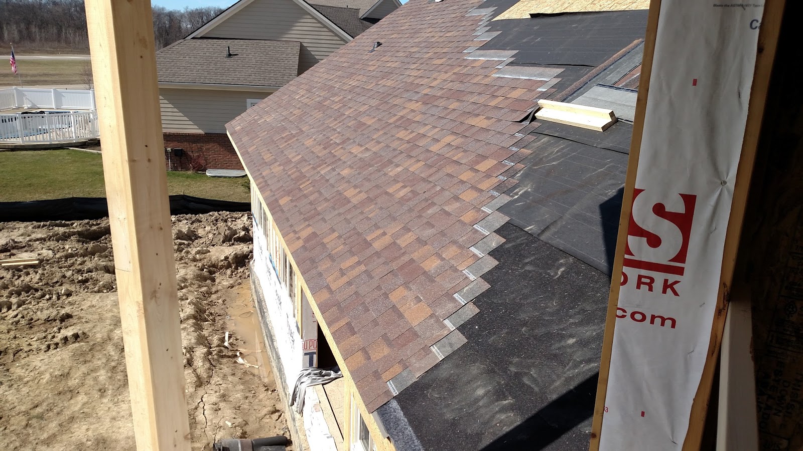
In early March, out builder let us know that we needed to be selecting our shingle color.  So, we set off to the designated supplier.  We decided to go first to the designated brick supplier to select the type of brick.  I had no idea there were so many choices.  After picking out our bricks, we took a brick sample and a window color sample to the shingle supplier.  The supplier set out samples of the various colors available in the brand specified in our contract with our builder.  Some of them looked great by themselves but none of them looked quite right with the brick.  Looking at some other brands, we found a sample with a mixture of colors that seemed to pull everything together.  Not surprisingly, it was a bit more expensive than the brand in our contract.  A few days later, the crew was busy installing them.

This is taken from the master bedroom as the shingles are being installed.  The variation in color is much more apparent up close than from a distance.

The hangar in the midst of the shingling process.

Th hangar after the shingles have been installed.

The front of the house after the shingles have been installed.

The back of the house after the shingles have been installed.


Sunday, March 20, 2016

Windows

We selected Inline Fiberglass windows and sliding glass doors from Canada.  A favorable exchange rate made these windows more affordable than lower performing windows from more common choices.  Most of the windows are casements.

Window performance is characterized by three values.  The U-value (reciprocal of R-value) indicates the heat conductivity (lower numbers are better).  The Solar Heat Gain Coefficient (SHGC) indicates the percentage of radiant heat that is transmitted.  Higher SHGC implies that the house will gain more heat from the sun, which is good in winter but can be bad in summer.  Finally, the Visable Transmittance (VT) indicates the percentage of visible light that is transmitted.

Inline offers various glass coatings and other features that impact these values.  In the back of the house, which faces South or Southeast, we selected an option with high SHGC to provide plenty of solar heating in winter.  The house is configured so that these windows are shaded in the summer when the sun is high.  In the front of the house, we selected options with slightly lower U-values to minimize heat loss.

Since we ordered the windows from a distant company, we weren't able to see samples beforehand.  It was a relief when they were delivered and I could confirm that they looked like I was expecting.

The diagram below shows a wall section through the window installation.  Inline allows for several different ways of installing their windows.  We went with a brick mould style nailing fin so that the windows can be nailed to the framing through the foam.  The detail is slightly different for the windows in brick walls.


A rough opening
The outside of one of the guest bathroom windows
The inside of the office window
A close-up of one of the kitchen windows
The front door was installed at the same time.
The inside of the front door

Saturday, March 19, 2016

Exterior Foam

As discussed in a previous post, the exterior walls of the house (but not the garage and hangar) are to be covered with a layer of rigid foam.  With the roof mostly framed and sheathed, the crew began working on installing this foam.  The portions that will have siding have furring strips over the foam.

Front view of the house after foam installation.  The second floor wall has not yet been covered with Tyvek housewrap and furring strips, but will be eventually.  The section on the right and the portion under the windows will have brick, so they do not have furring strips.  The windows are waiting in the garage,
This view shows several of the steps.  The black ribbon is a peel-and-stick membrain that prevents air leakage through the second floor rim joist.  The white tape over the OSB seams make the OSB a better air barrier.  The 2" of foam have been installed in the bottom portion of the picture.  Tyvek and furring strips have been installed over the foam on the section on the left.
A screen and mesh is installed along the bottom of the furring strips to keep insects from crawling behind the siding.
The gable walls are not covered with foam.  The end truss is positioned such that the gable wall lines up with the furring strips so that the siding will be continuous,

Note the airplane taking off from behind the house - a view I hope to be seeing many times

Sunday, March 6, 2016

Trusses


Just before our family vacation, the trusses were delivered and walls were ready to support them.


While we were vacationing in Florida, the framing crew was at work setting the trusses. We hear there was a snowstorm that may have slowed things down.  When we returned, the trusses were in place over the residential portions of the house.

Front view after the first week of truss work.
Rear view after the first week of truss work.
Next, the trusses were set over the garage and hangar.  This week's snow didn't slow things down very much, but I am still sick of it.

Rear view after the second week of truss work.  The trusses over the hangar are two piece trusses.  The top piece is not yet installed in this picture.
Front view after the second week of truss work.
This shows the raised-heel scissor trusses in the family room that will support a sloped ceiling and still allow a full layer of cellulose insulation all the way to the edge of the attic.
These trusses over the half bath allow space for the rigid foam on the outside of the master bedroom wall.